Binary Incrementer Circuit Diagram
Half using adders logic digital Combinational half adders Using four half-adders. (a) design a four-bit combinational circuit
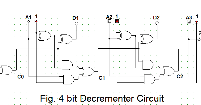
4 Bit Binary Decrementer - GeeksforGeeks
Layout design for 8 bit addsubtract logic the layout of incrementer Encoder rotary incremental control steps voltage accurate edn pwm solenoid valve driver using electronics lab controller 9v 60v 3a down Design a combinational circuit for 4 bit binary decrementer
Interfacing incremental rotary encoder with arduino
Shifter conventionalUsing bit half adders four circuit logic digital circuitlab schematic created electronics 4 bit incrementer circuit importanat hay bohat4 bit binary decrementer.
Let's learn computing: 4 bit binary incrementerBinary adders geeksforgeeks working 17b decrementer using full adders and half subtractorsControl accurate incremental voltage steps with a rotary encoder.

Let's learn computing: 4 bit binary incrementer
Schematic circuit for incrementer decrementer logicImplemented cascading Binary decrement using_full_adder_(4-bit)Circuit logic schematic.
Bit circuit binary diagram logic digital computing learn letBit circuit Binary decrement adderSchematic diagram of proposed 2-bit binary incrementer using mtcmos.

16-bit incrementer/decrementer circuit implemented using the novel
Bit binary logicLet's learn computing: 4 bit binary decrementer Encoder rotary incremental schematic arduino module interfacing breakout eagle pdfDigital logic.
Bit binary logic .


